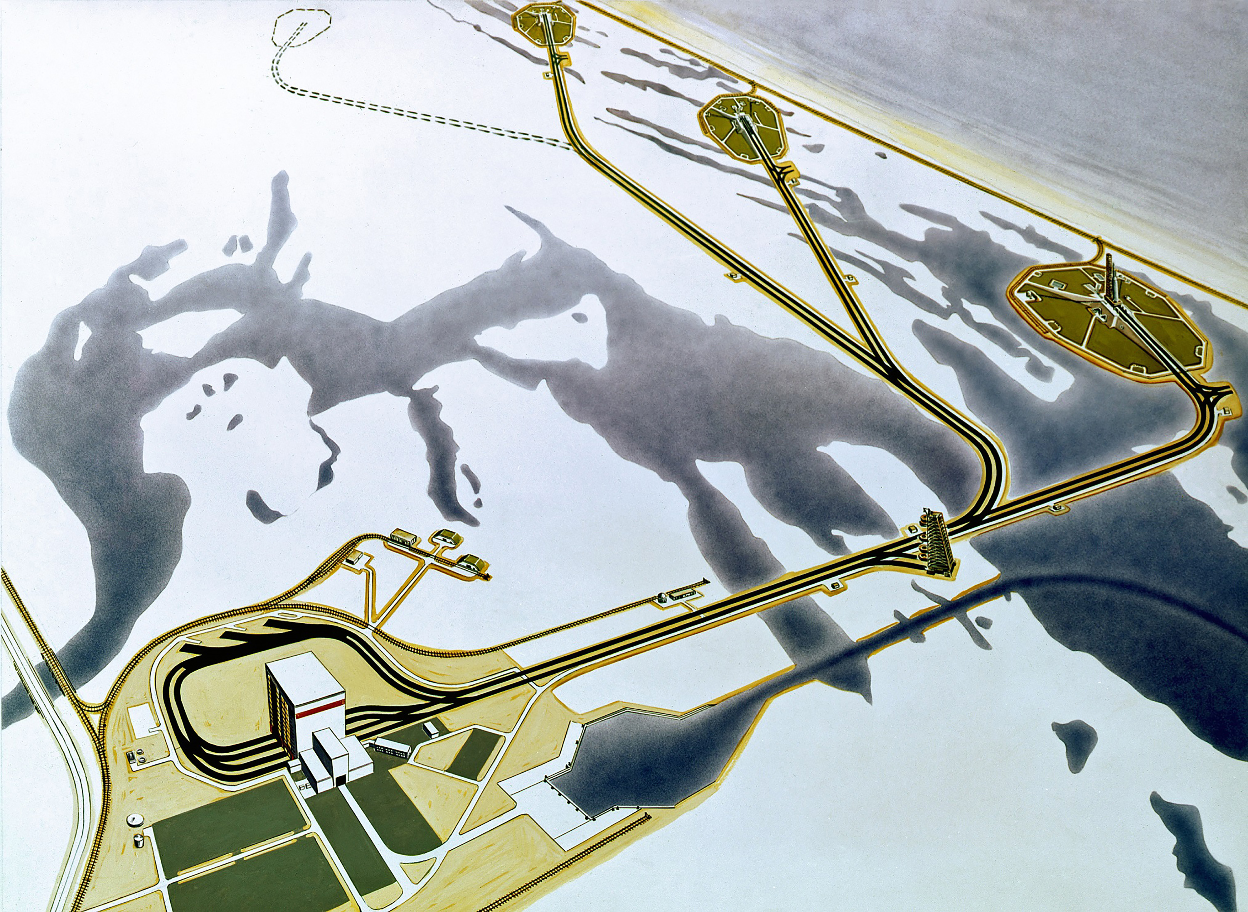
The iconic launch pads, Pads 39A and 39B at Kennedy Space Center’s Launch Complex 39, have been the starting point for many space flights including the first manned lunar landing. The original design for Launch Complex 39 called for three to five launch pads, designated 39A – 39E, that would have been spaced approximately 1.6 miles apart to protect them from damage if any mishaps occurred at an adjacent pad. Also part of Launch Complex 39 is the Vehicle Assembly Building, or VAB. Towering more than 500 feet, it can be seen easily from miles away. The Launch Control Center, or LCC, where all the launch controllers, support personnel, and equipment required to safely launch a vehicle from either of the launch pads is also a part of the large complex.
Pad 39A from sand to Apollo
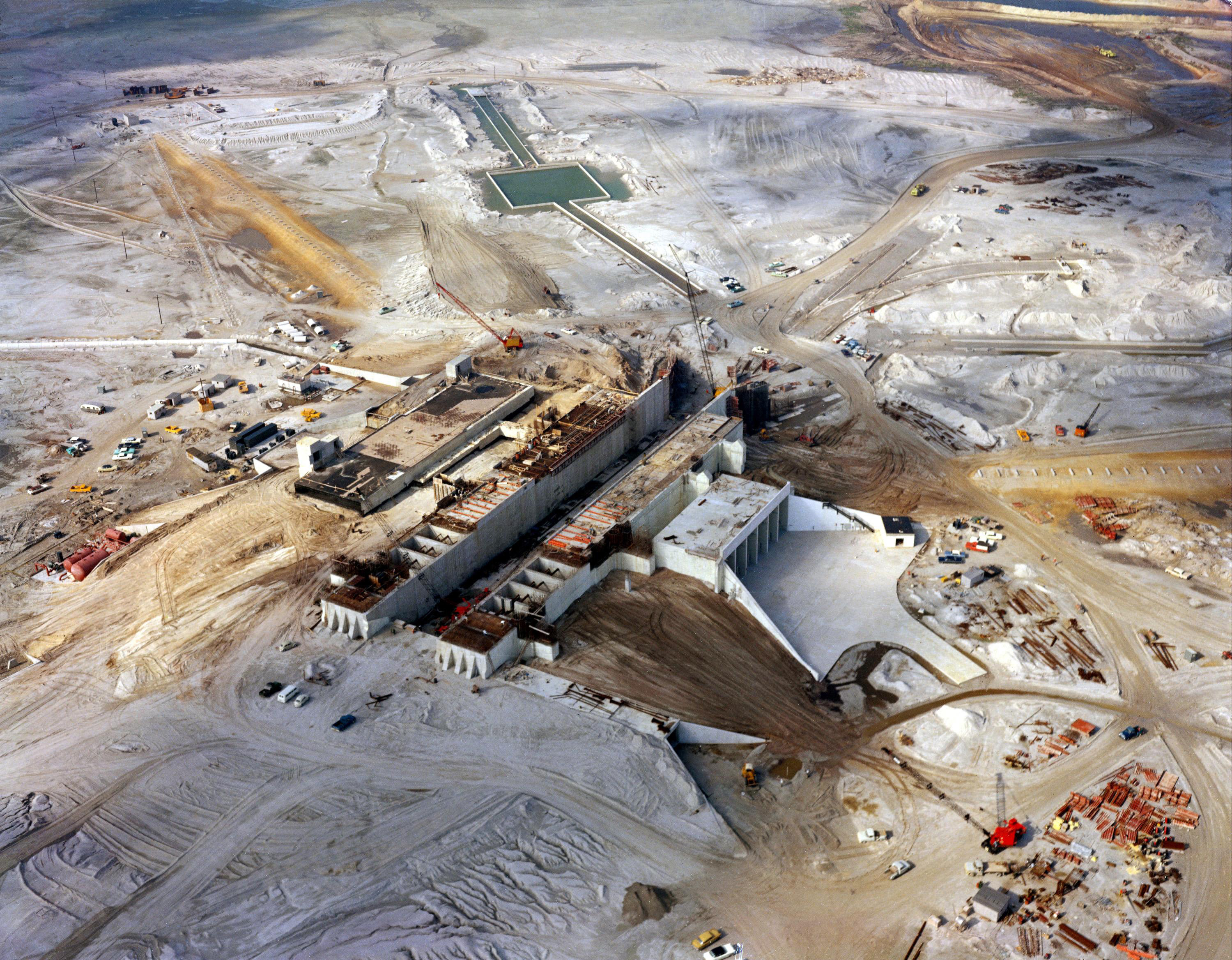
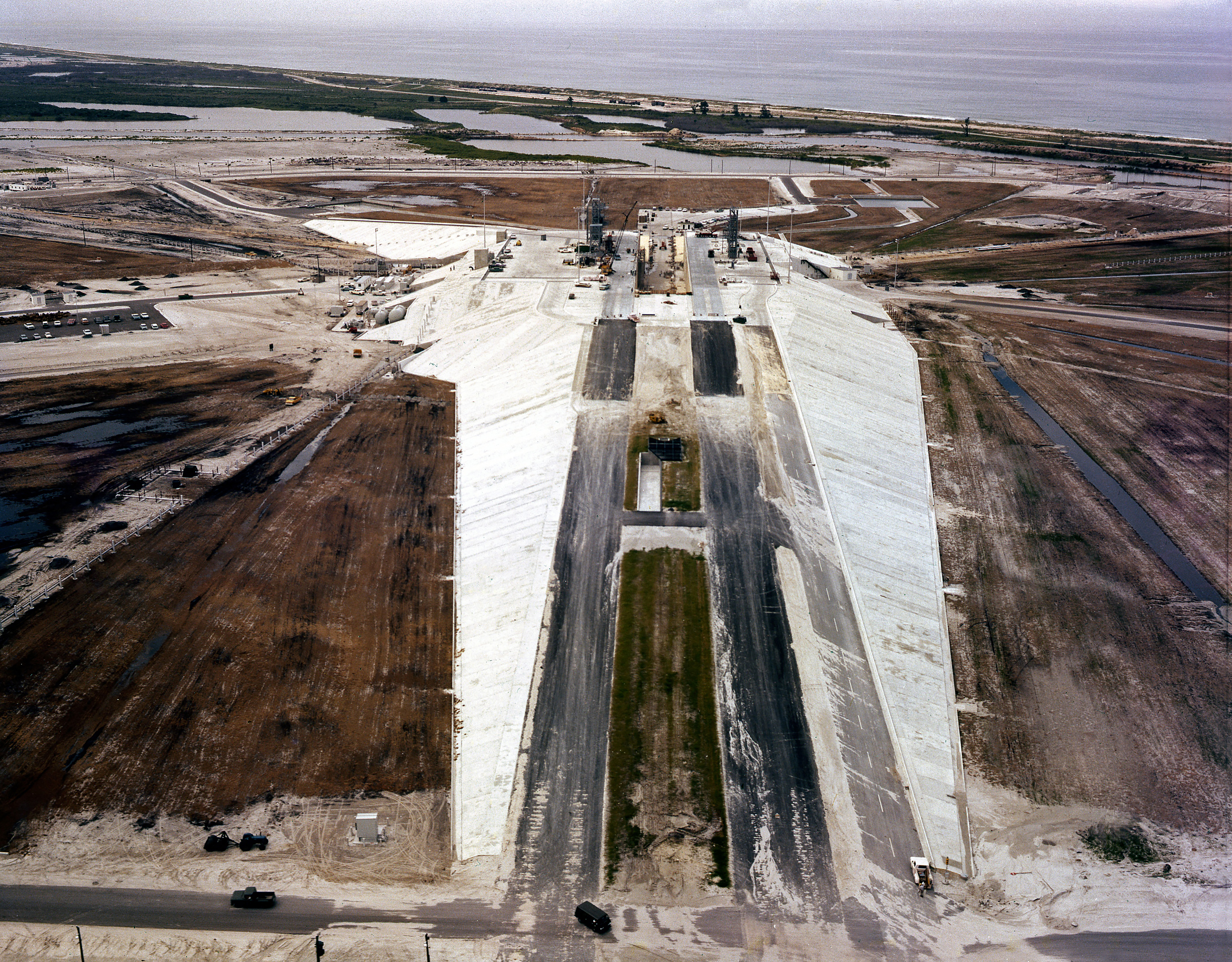
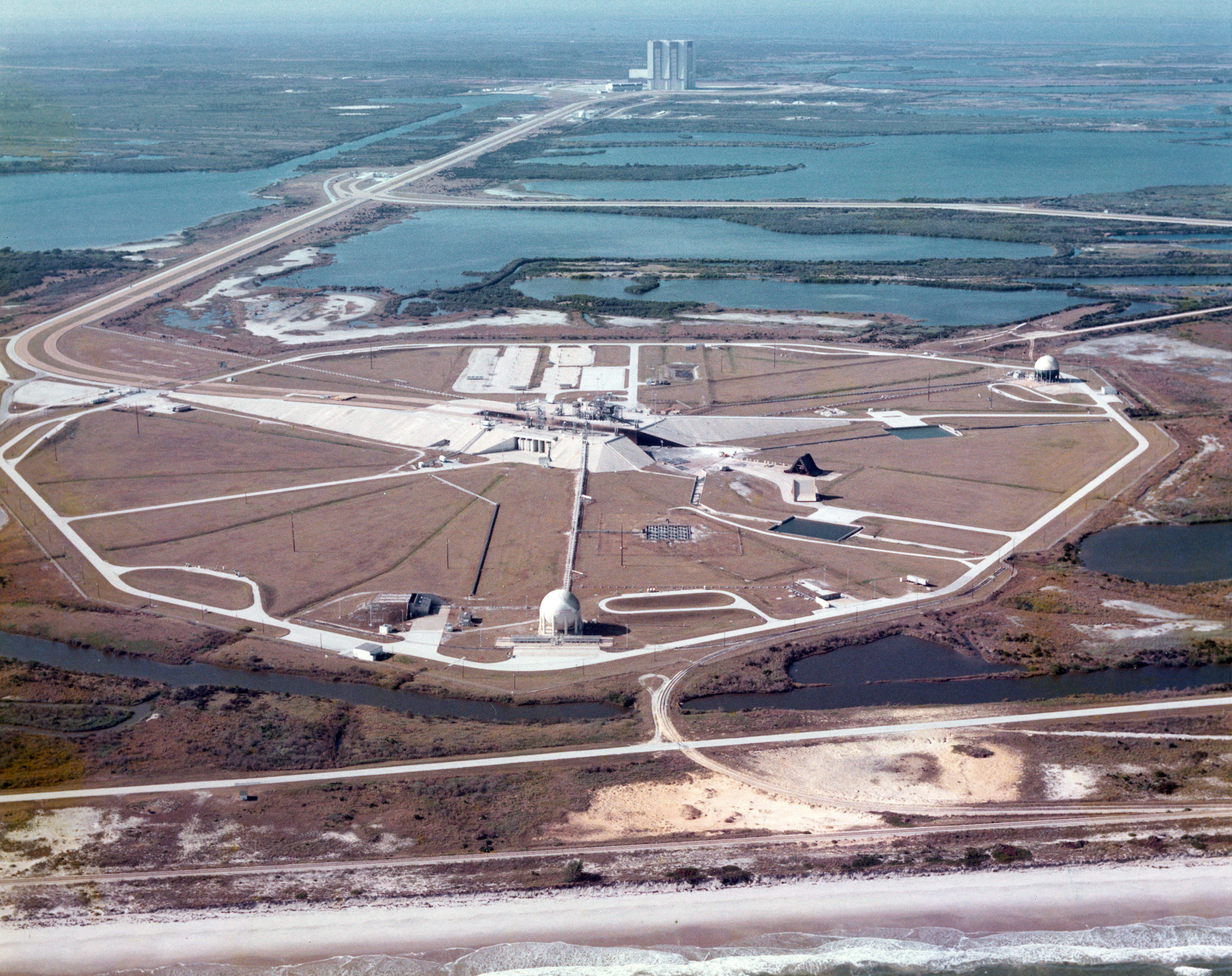
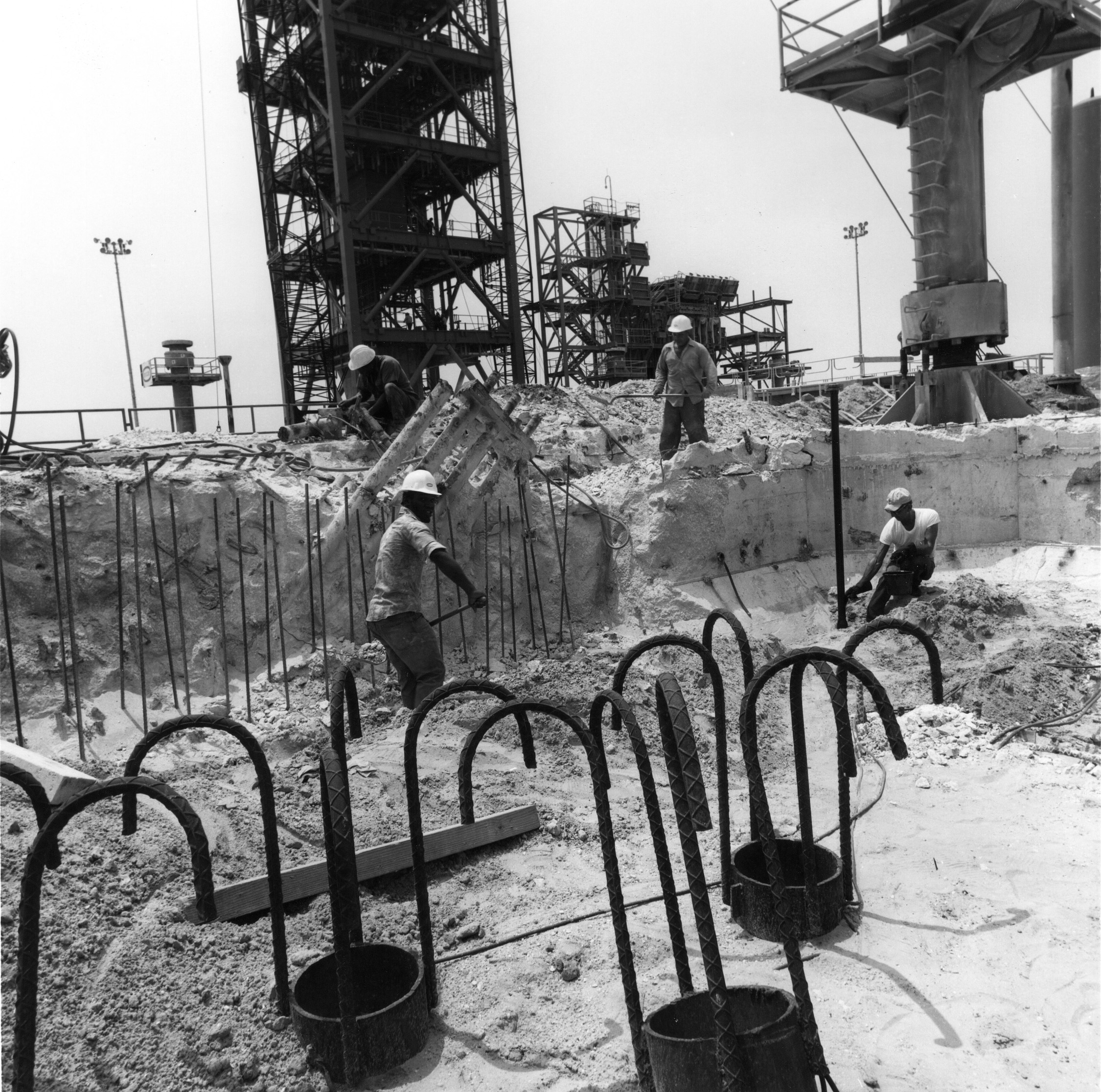
Pad 39A was originally designated to be Pad 39C in the complex’s original plan, however it became 39A when plans to build the three additional pads were scrapped in 1963. Launch Complex 39’s A pad was completed first. Construction began in November of 1963 and was completed in early September 1965. Built on around a quarter square mile of land, the launch site is an eight sided polygon and measures 3,000 feet across. The pad itself is 390 feet by 325 feet and is constructed of reinforced concrete. The hardstand stands 48 feet above sea level. To get from sea level up to the hard stand, a five-percent sloped ramp was constructed. Which raises the question, “Why build up and not down to avoid having to have a ramp up to the pad?”. The answer is simple, the pads are located in Florida just a quarter mile away from the Atlantic Ocean, and digging down just a few feet you will encounter water. So to protect all the equipment and facilities that are under the pad, the decision to build above ground was made.
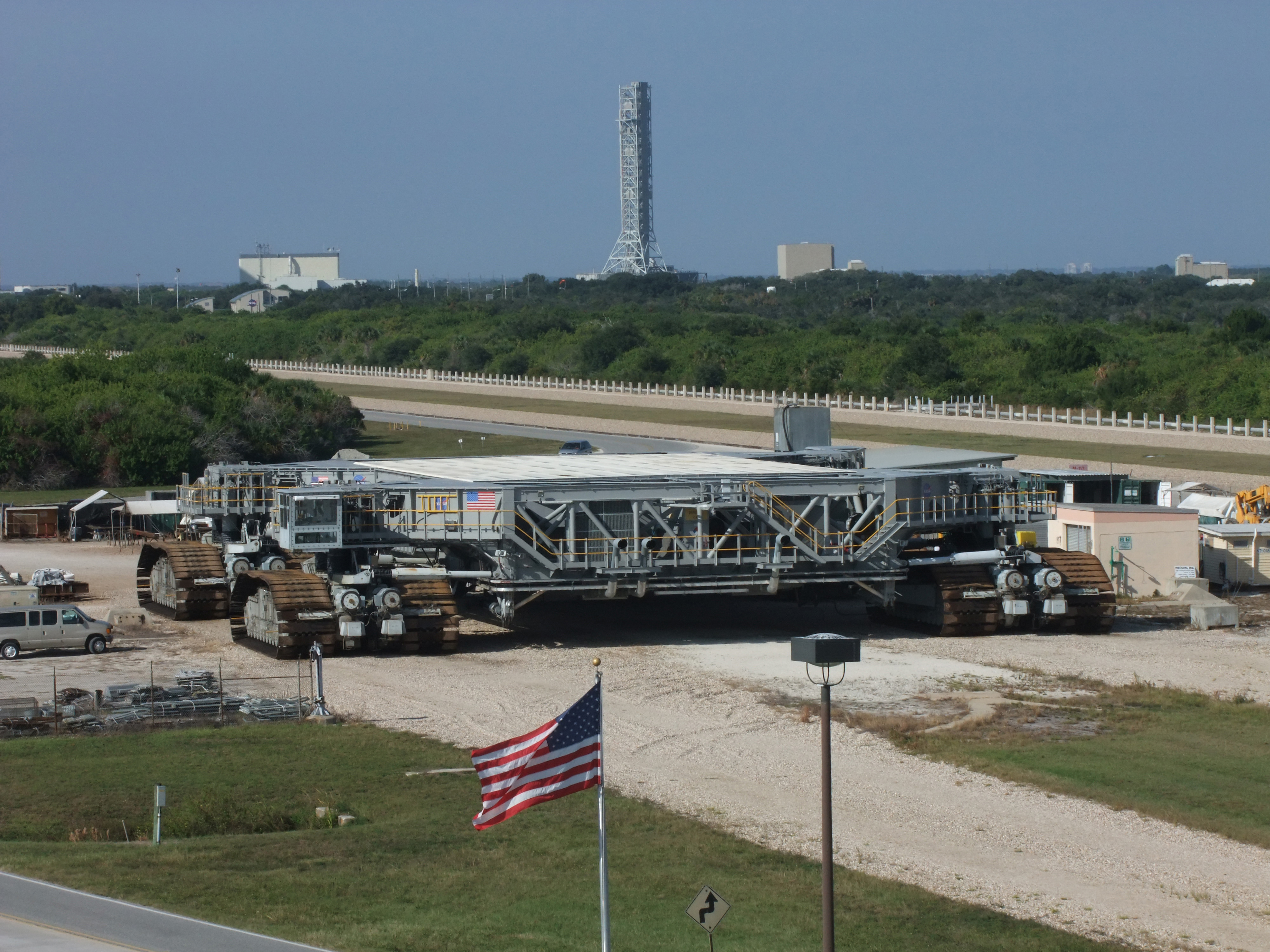
For Apollo, the pad would be a clean pad, no structure, towers, or other support equipment was located on top of the pad. All these items would be brought with the vehicle. The vehicle was assembled on a massive platform known as a Mobile Launcher. On the Mobile Launcher was a Launch Umbilical Tower (LUT) and a mobile service structure which allowed for crew access, all the umbilical connections for the rocket, elevators, service platforms, everything you needed to get the vehicle ready for launch on the pad. The Mobile Launcher was transported by a new vehicle, called the Crawler, from the Vehicle Assembly Building out to the pad. The Mobile launcher would be lowered onto pedestals located atop the hardstand.
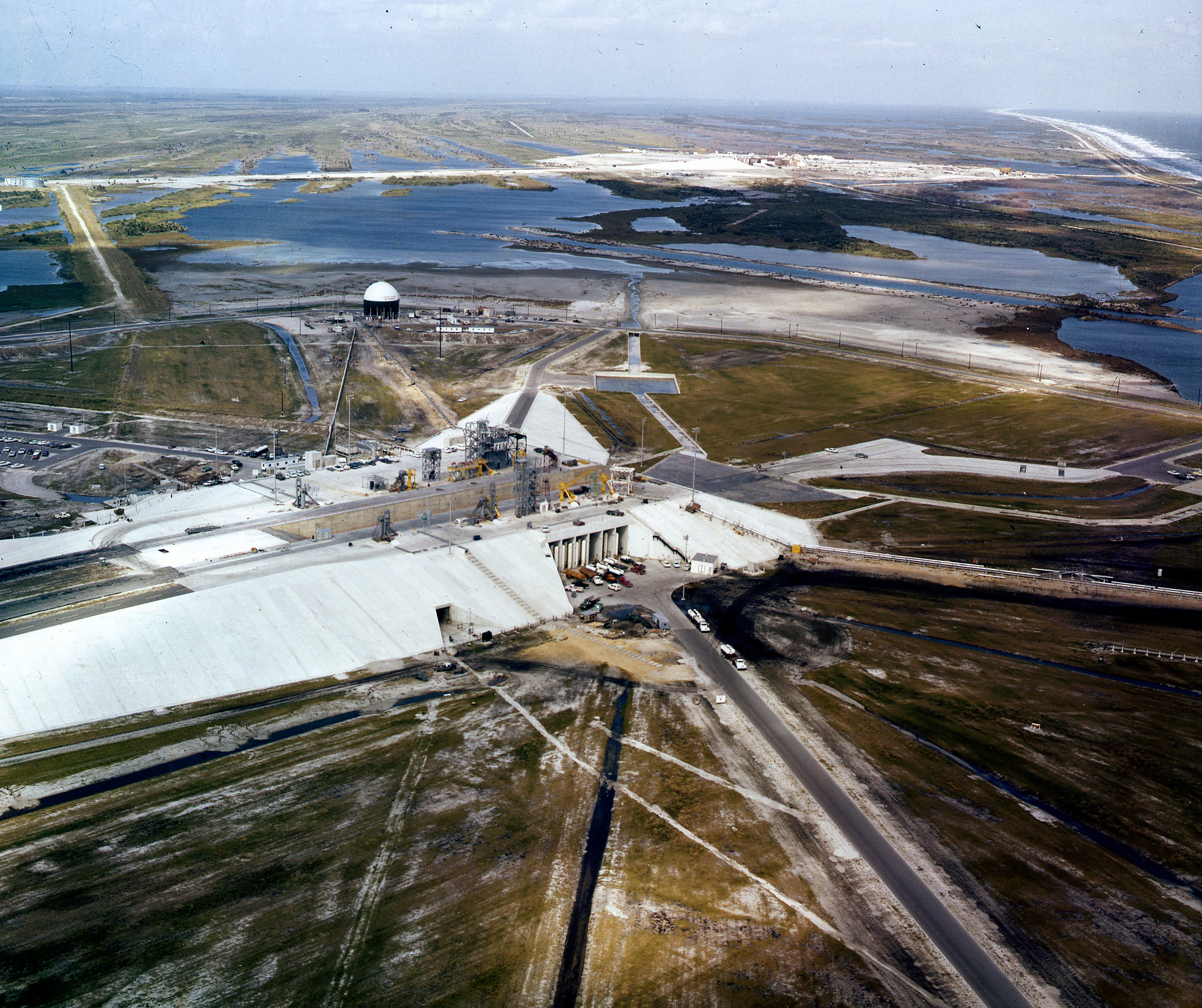
Without the Mobile Launcher at the pad, from the outside mostly what you see at Pad 39A is the pad itself, however much more lies beneath the exterior. A two-story pad terminal connection room which houses all of the electronic equipment that would connect the Launch Control Center with the Mobile Launcher when it’s on the pad, is located on the western side of the pad. Also on the same side is the environmental control systems room which supports the air conditioning and water systems. Beneath the east side of the pad is the high-pressure-gas storage facility, where nitrogen and helium gases piped from the converter-compressor facility would be distributed from. Dissecting the east and west sides is the 58 foot wide, 450 foot long, Flame Trench. A Flame Deflector, weighing some 700 tons, would be rolled into place via a rail system in the Flame Trench until it was just under the rocket. The deflector directed the flames down the trench and away from the vehicle and pad.
Also located inside of the pad area is a blast room. If a hazardous condition came up that required the Apollo Astronauts to egress from the spacecraft, they would move from the spacecraft back to the Mobile Launcher’s tower and ride the high speed elevator down 30 stories, in about 30 seconds. Then they would slide down an escape tube to the blast room. The blast room has thick steel doors which could withstand the explosion if the vehicle erupted on the pad. The crew could survive for at least 24 hours in the blast room until they could be rescued.
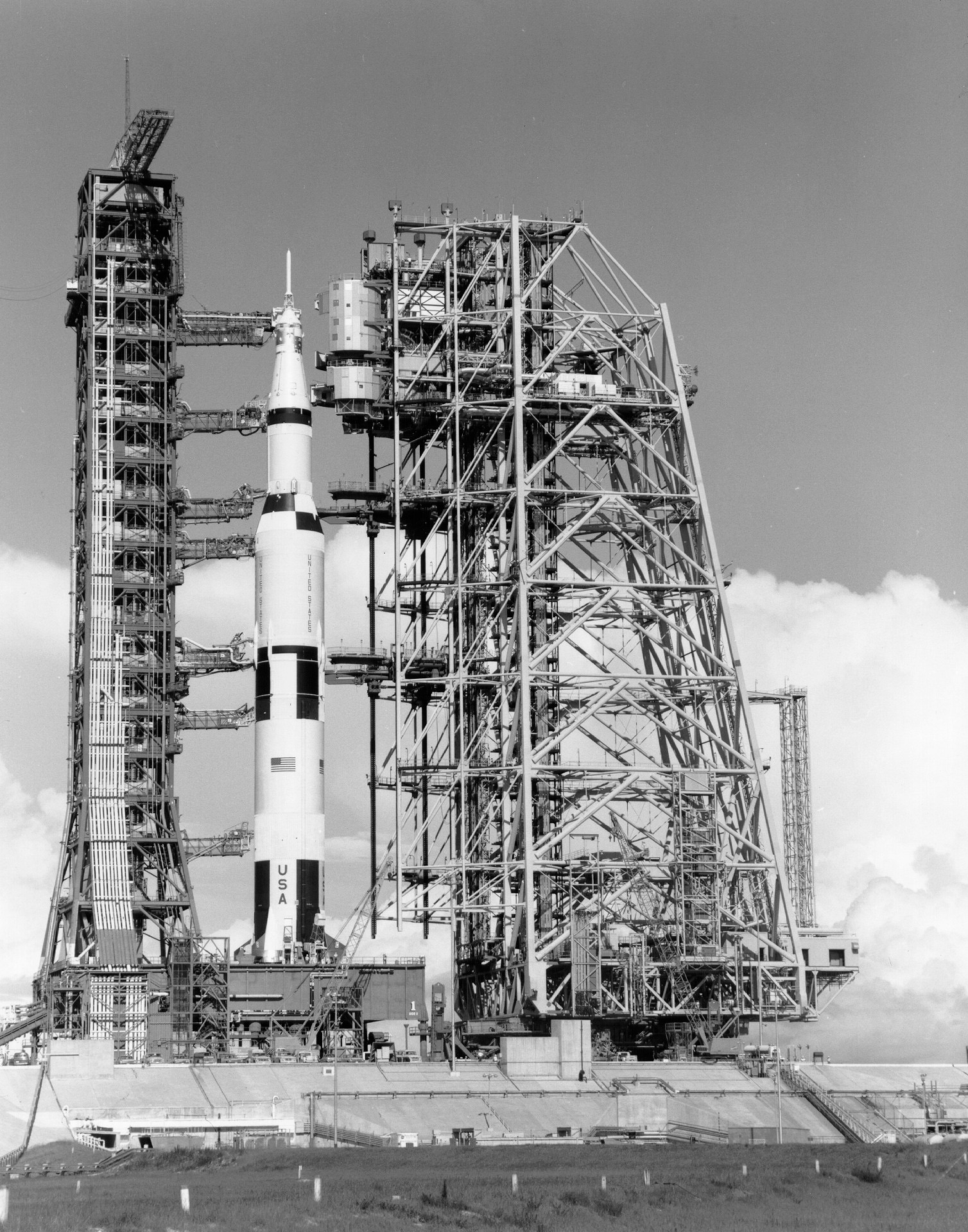
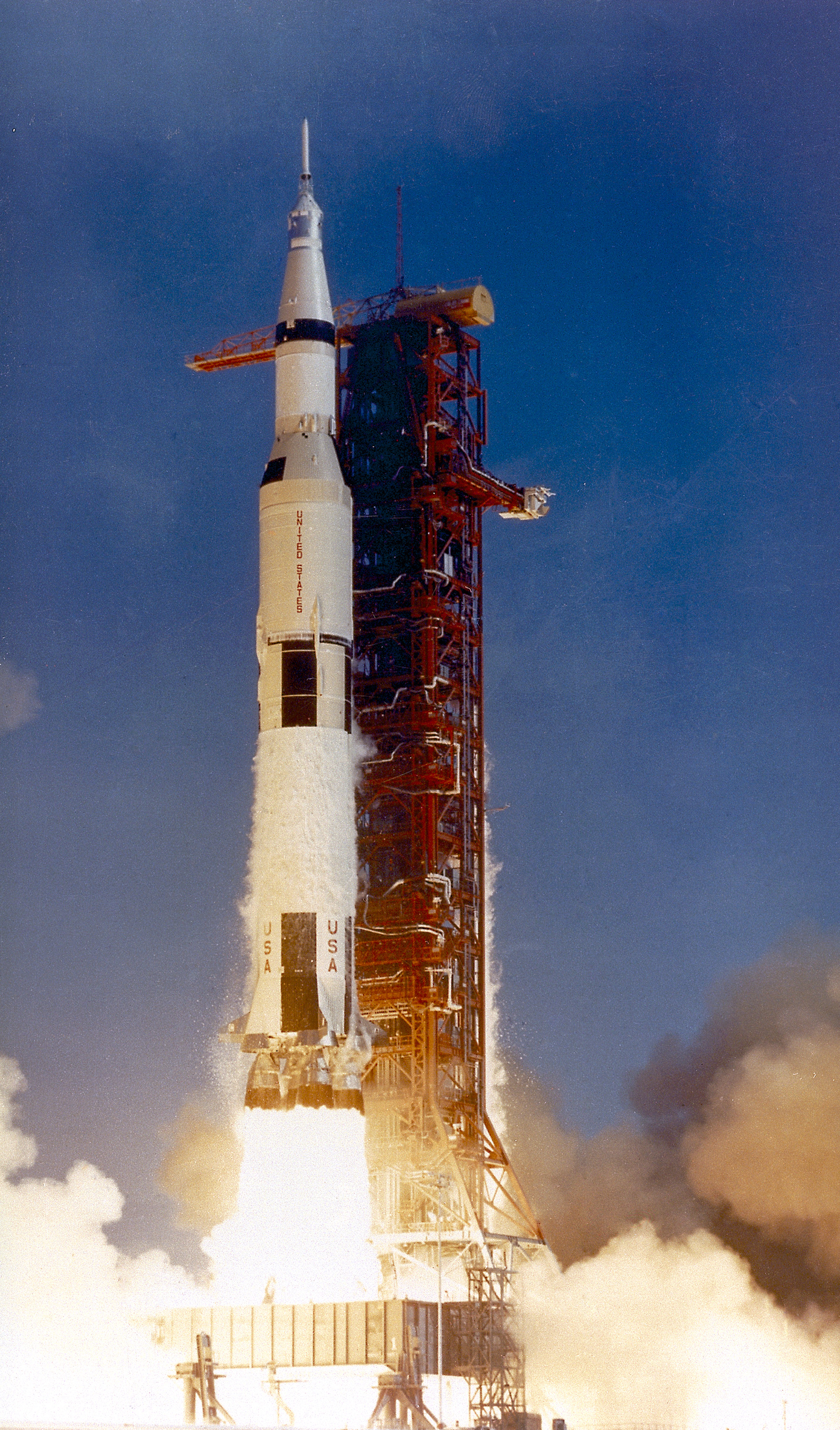
The first flight from Pad 39A would be Apollo 4, an unmanned test of the great Saturn V rocket. Following it would be another unmanned test, Apollo 6. The third launch was the historic first trip to the moon, Apollo 8, which took Frank Borman, Jim Lovell, and Bill Anders on a trip to the moon where they did 10 orbits before coming back to Earth. And the fifth launch from Pad 39A would be Apollo 11, the first manned Lunar landing when Neil Armstrong and Buzz Aldrin became the first human beings to step on another space body. Pad 39A would be the starting point for every Saturn V mission except for Apollo 10 which launched from Pad 39B. Twelve flights of the Saturn V started at Pad 39A and half of them were the manned lunar landing missions. The pad’s significance as a historical landmark will never be in question due to the fact the first manned landing missions to the Moon all began there. It also served as the launch pad for the Skylab orbiting outpost – our first space station – which was also the last flight of the Saturn V rocket and the last mission to launch from Pad 39A for more than six years.
From Apollo to Space Shuttle
Shortly after Skylab launched, modifications to the pad began for the next step in our continuing exploration of space. The Space Shuttle program had been approved before the Apollo missions were even finished. In fact, Apollo 16 Commander John Young and his Lunar Module Pilot Charlie Duke were walking on the surface when word came up from Mission Control that the budget had passed, including the vote for the Space Shuttle program.
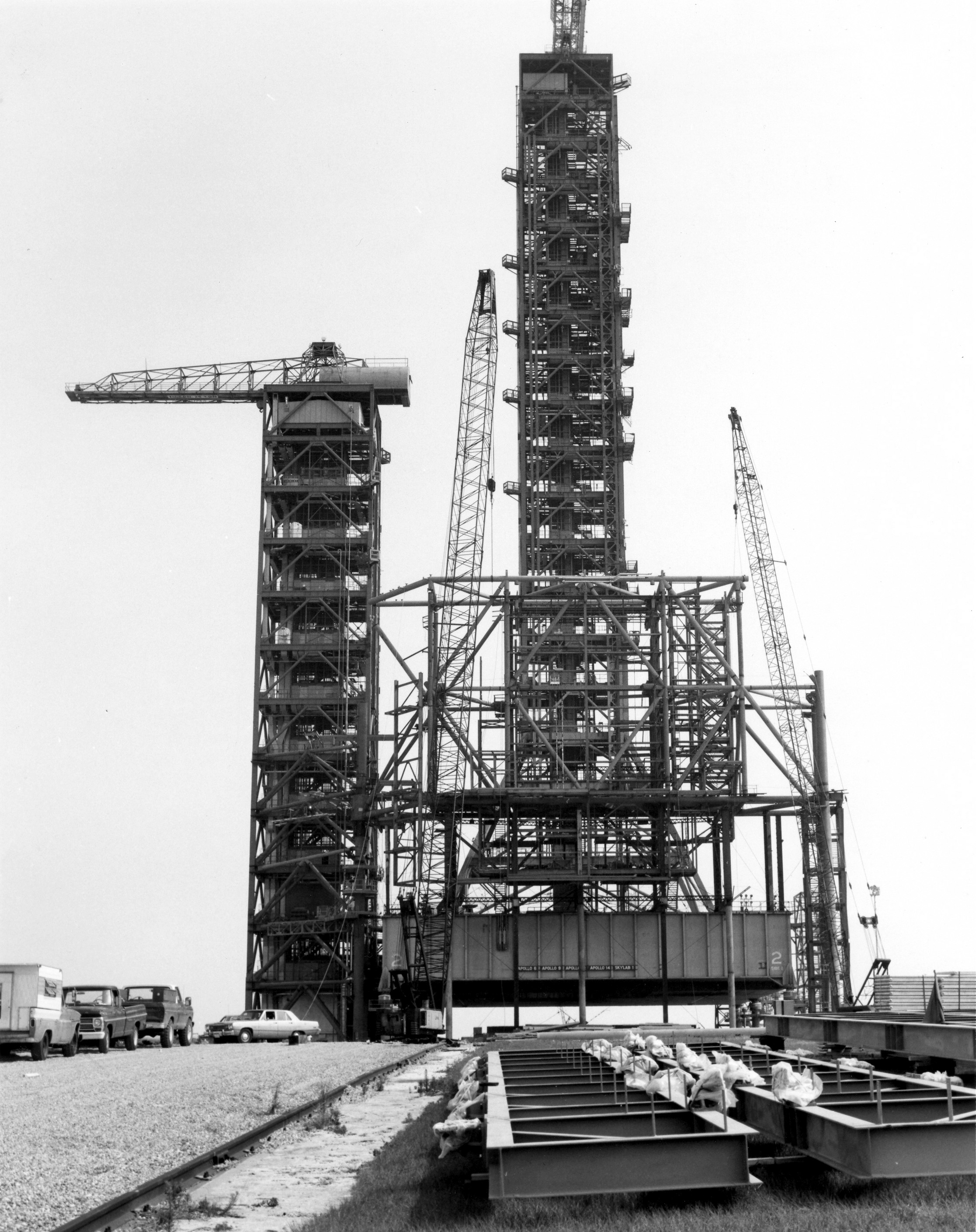
The Shuttle would be a totally different vehicle than the mighty Saturn V and Saturn 1B rockets that had flown from Launch Complex 39 up until now. While the new vehicle would be less than two thirds the height of the Saturn V, its design required a complete reconfiguration of the Pad structure and the mobile launcher. A lot of work on the ground had to take place before the Shuttle would ever fly.
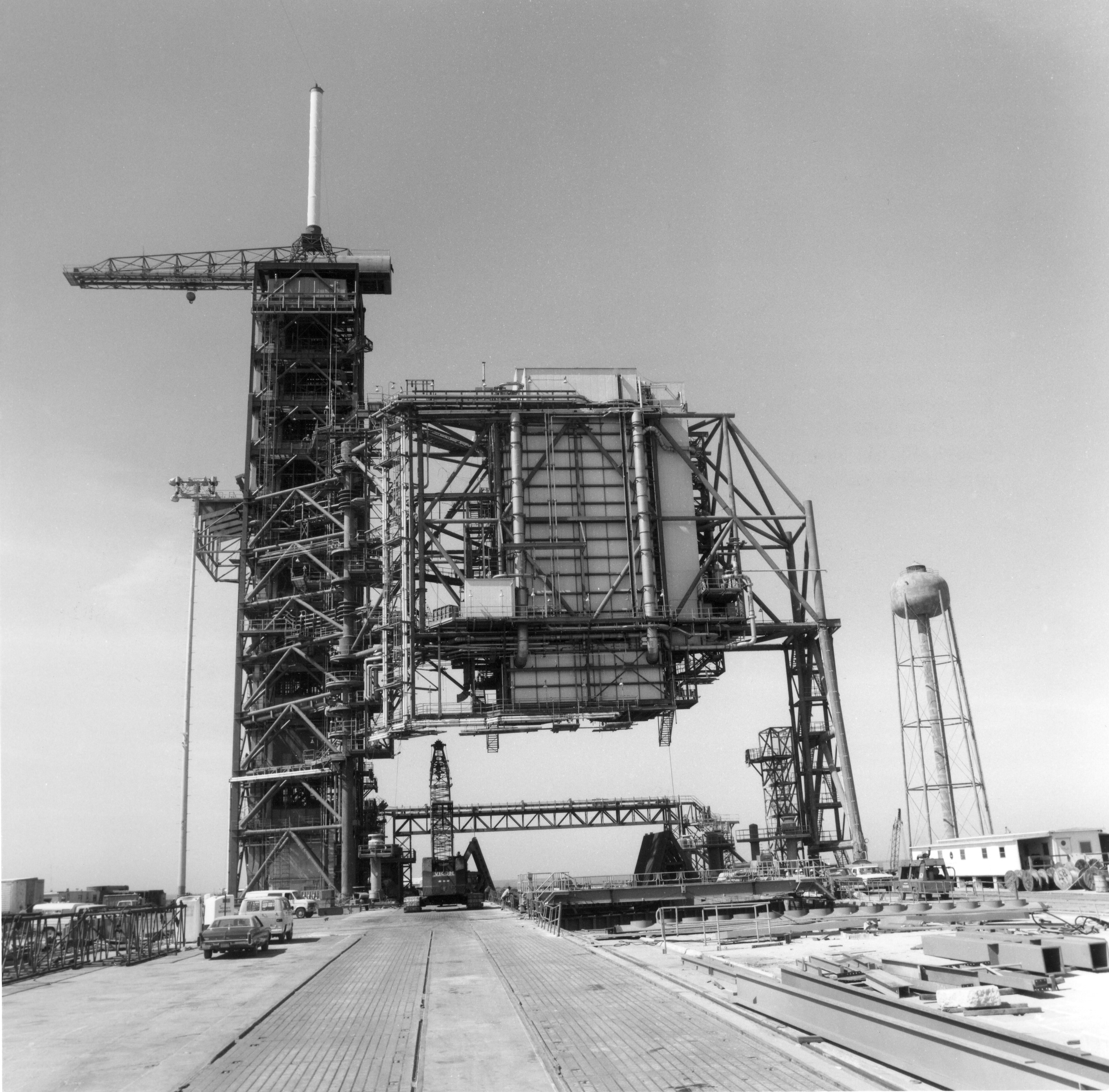
The pad would now be the permanent site for the umbilical tower, or as it was now called the Fixed Service Structure (FSS). This was not a completely new structure however, the upper portion of Launch Umbilical Tower (LUT) that Apollo used was removed from the Mobile Platform and installed on the Launch Pad 39A’s hardstand to become the FSS. Standing 347 feet high, the new FSS would have 12 floors, 20 feet apart. Each floor is actually not solid, but metal grates, so looking down at your feet you can actually see down a number of floors. The exception is the 195 foot level where the crew accesses the orbit, it has solid floors because, well you’ll find out later in the story. It had three access arms that provided services or access to the Shuttle. On top of the structure was a new 80 foot tall lightning mast, and just below the mast, an Apollo era Hammerhead crane was installed to be used for any heavy lifting operations needed at the pad. The crane was removed in 1994 when cost analysis revealed it to be more cost effective to bring in mobile cranes when needed rather than to maintain the hammerhead crane.
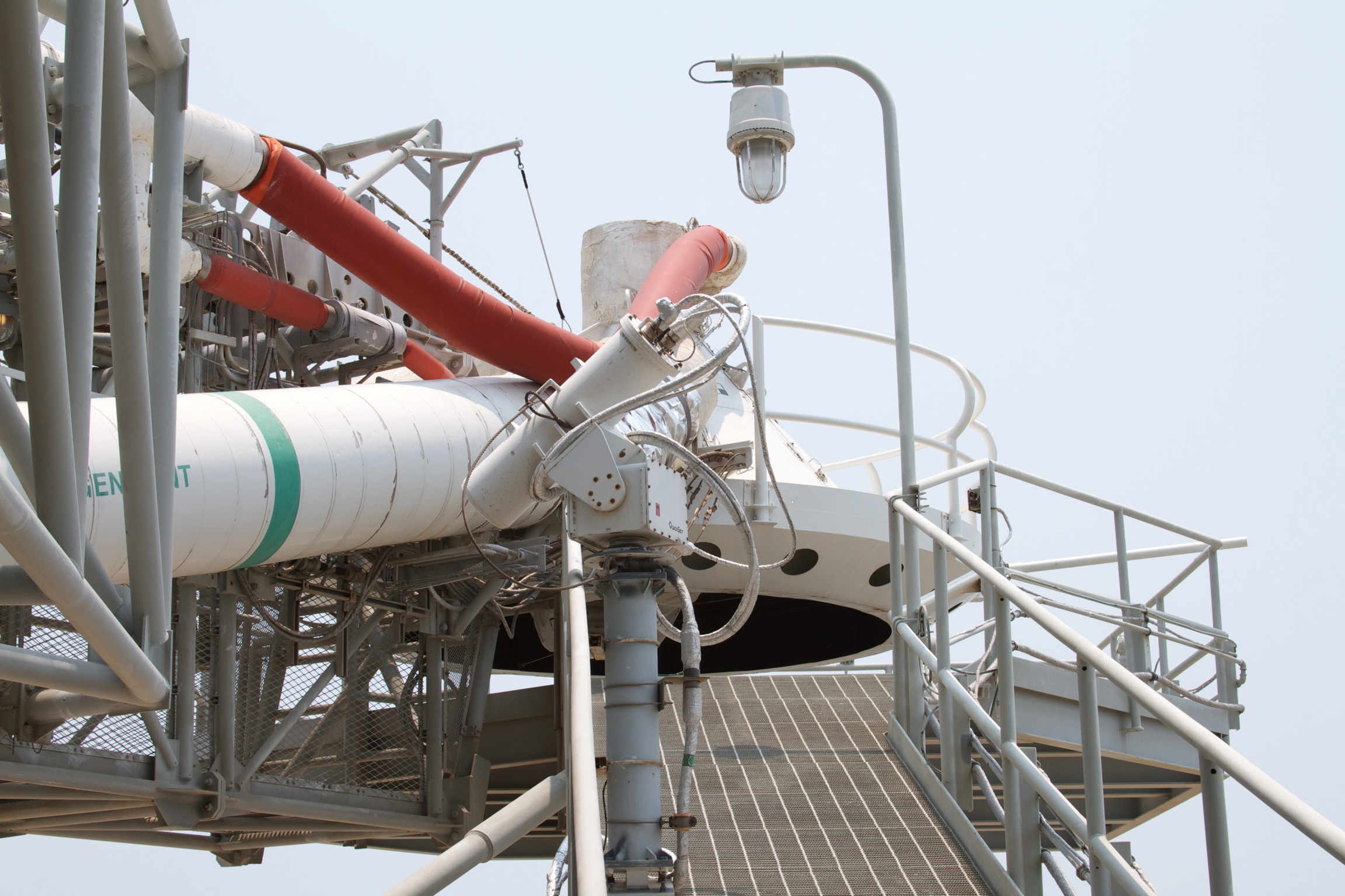
Located between the 207 foot and 227 foot level of the FSS was the Gaseous Oxygen Vent Arm. On the end of that arm was a 13 foot diameter hood, known as the “Beanie Cap”. The cap would heat gaseous oxygen that vented from the Shuttle’s External Tank that could freeze and form potentially dangerous ice. The oxygen travels just a few feet away from the hood where it is safely released into the atmosphere. The arm would be in place before fueling and would be swung away approximately 2.5 minutes prior to launch.
Headed down the FSS, we next find the External Tank Hydrogen Vent Umbilical and Intertank Access Arm located at the 167 foot level. The 48 foot long arm gives the pad crew access to the External Tank intertank compartment if needed. It also allows for mating of the External Tank umbilical and vent lines. Around 5 days prior to launch, the arm is retracted leaving just the umbilical vent line connected to the External Tank to support tanking and launch. The vent line part of the umbilical serves basically the same purpose as the Beanie Cap, except venting hydrogen from the tank. Also rather than releasing the hydrogen close by, it is taken through the line, into a venting system that takes it far away from the pad where it is safely burned off. The line itself detaches at first motion of the vehicle at launch and is pulled away downward away from the vehicle and secured.
Finally at the 147 foot level you would find the Orbiter Access Arm. At 65 feet long, 5 foot wide, and 8 feet high, it’s the largest arm on the FSS. This metal bridge provides access to the crew compartment of the orbiter. Located at the end of the arm is the “White Room,” an environmentally controlled chamber which mates with the orbiter and can hold up to six people. After the crew is loaded and all the pad personnel have left, the arm remains in place until 7 minutes and 24 seconds prior to the launch to serve as an emergency escape if needed. After that time it can be repositioned in about 15 seconds if any emergency arises.
Fueling of the Shuttle required a lot of propellant as the External Tank held over 500,000 gallons of propellants. Two spheres on opposite sides of the pad perimeter, approximately 3,000 feet apart, held the propellants until they were pumped into the Shuttle’s External Tank. One tank could hold up to 900,000 gallons of liquid oxygen at –297 degrees Fahrenheit while the other tank could hold 850,000 gallons of liquid hydrogen at –423 degrees Fahrenheit. The propellants were transferred from the storage tanks in vacuum-jacketed lines that feed into the orbiter and External Tank via the tail service masts on the mobile launcher platform.
The Apollo blast room was mothballed and instead a new Emergency Egress System was installed. The new system was located at the 195 level of the FSS, the same height as the Crew Access Arm, and is a slide wire system with baskets for astronauts and pad workers to speedily escape the pad in the event of an emergency. In 135 launches, the system was never used, however if it had been, fire nozzles would release heavy sprays of water over the pad area. Remember earlier I mentioned how the 195 foot level had a solid floor? The water spray would be so heavy that the crew and pad personnel would only be able to see their feet and the floor, so a bright yellow pathway was painted on the floor, sometimes humorously referred to by the pad and crew as the Yellow Brick road, this would lead them to the escape baskets.
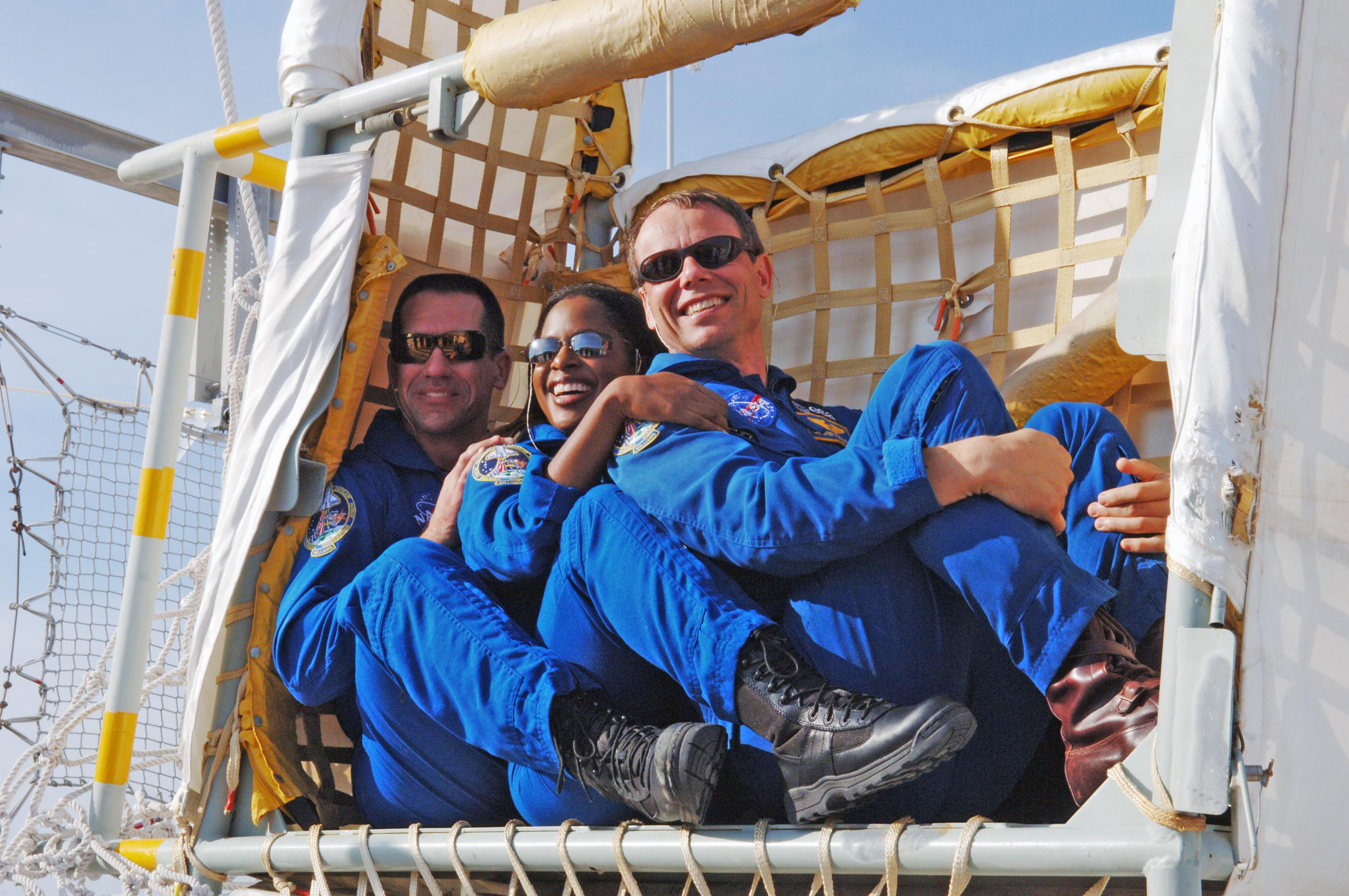
Seven baskets and slide wires were in place, each basket capable of transporting three people to the ground some 1200 feet to the west of the pad in just 90 seconds. The basket would reach a top speed of 55 MPH and would be slowed by a drag chain before coming to a complete stop in the catch net at the end of the system. When reaching the ground, the crew and pad personnel would find a bunker and one or more M-113 Armored Vehicles. In the event of an imminent detonation, the bunker could provide the best protection; otherwise they would board the M-113 Armored Vehicles and make a hasty departure to a safe zone more than a mile away from the pad.

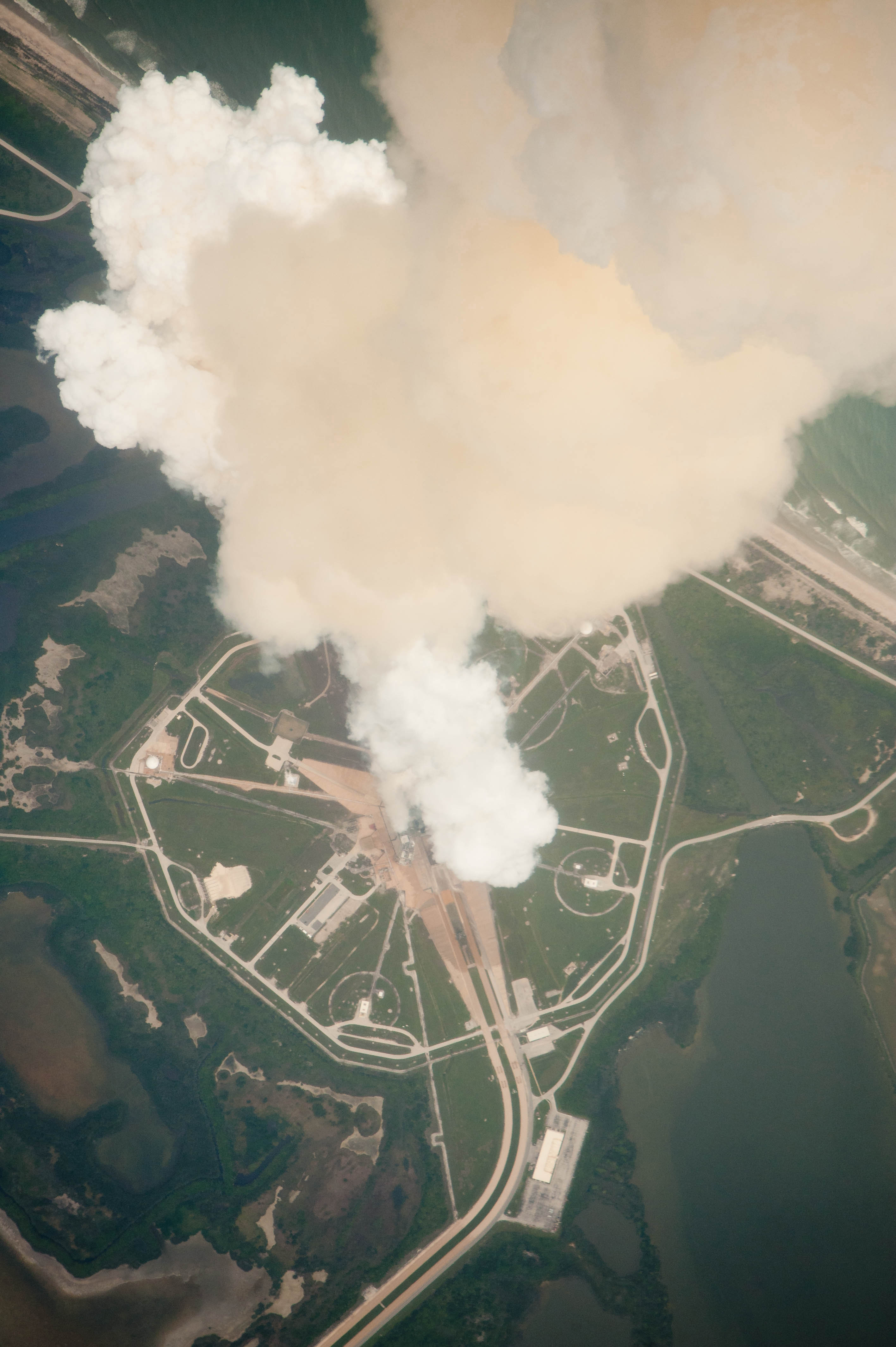
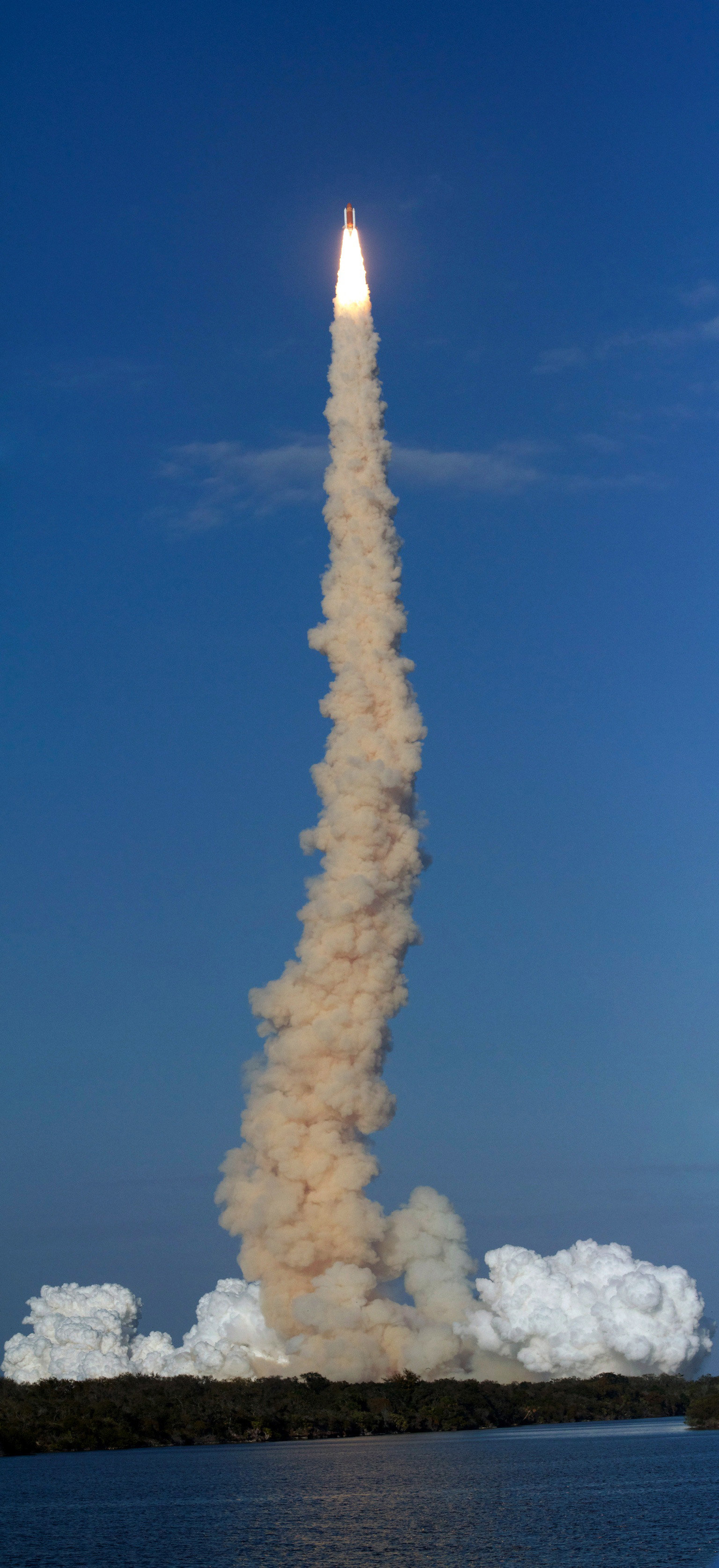
Another addition to the pad would be the Sound Suppression Water System. With the orbiter so close to the Mobile launcher, the sound waves produced by the three Space Shuttle Main Engines and the massive Solid Rocket Boosters upon ignition could have possibly damaged anything in the orbiter’s cargo bay and possibly the orbiter itself. The solution was to reduce the sound waves with a flow of water over the Mobile Launch Platform and the pad itself. A 300,000 gallon water tank located on the northeast side of the pad contains the water used in the system. Using gravity alone, the water is dumped onto the MLP and the Flame Trench of the pad via a system of quench nozzles, also known as “rainbirds”. When a Shuttle would launch, the intense heat from the engines would turn much of the water into steam, resulting in the large white cloud seen around the pad prior to booster ignition.
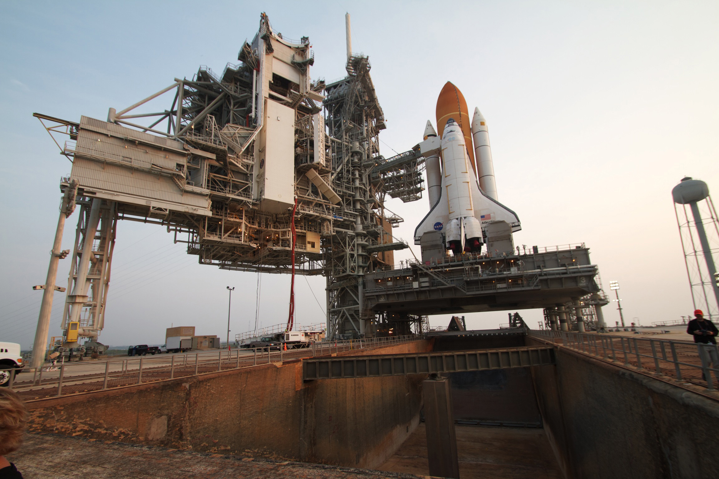
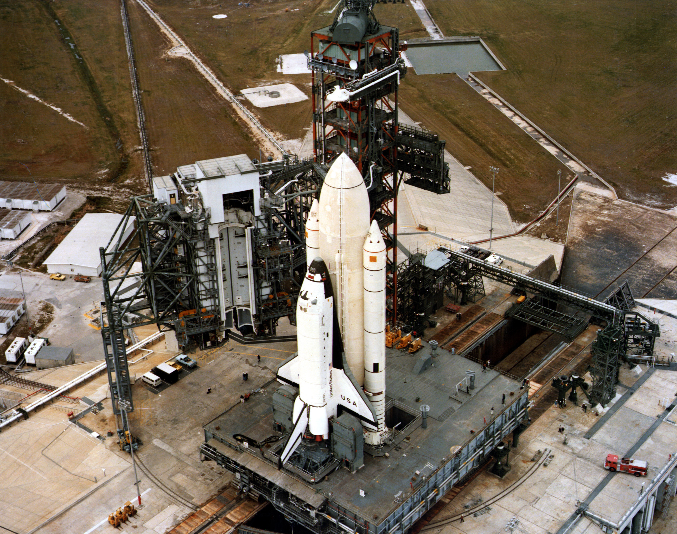
Attached to the FSS is the Rotating Service Structure or RSS. The main purpose of the RSS is to allow installation and servicing of the Shuttle’s payload for that mission, at the pad. It also allows technicians access to certain systems on the orbiter. A typical Shuttle launch begins a month or so prior to liftoff when the Shuttle, aboard the Mobile Launch Platform, is moved to the pad. Having payload installation at the pad allows the payload to be loaded much further along in the launch processing.
Measuring in at a healthy 102 feet long, by 50 feet wide, and 130 feet high, the RSS is quite a sight on its own. It rotates 120 degrees and is moved away from the Shuttle well before fueling and launch. The Payload Changeout Room is the main feature of the RSS. It’s an environmentally controlled area that is enclosed and supports the delivery of the payload to the orbiter’s payload bay. Also if the payload requires any servicing at the pad it is performed there. Inside there are five platform levels that allow access to the payload.
Two other parts of the RSS, the Orbiter Midbody Umbilical Unit, and the Hypergolic Umbilical unit, provide access and service to two important areas of the orbiter. The first provides fluids to the orbiter’s reactant storage and distribution system as well as fuel for the orbiter’s three fuel cells. The Hypergolic Umbilical Unit supplies Hypergolic fuel and oxygen service lines along with helium and nitrogen service lines which supply the orbiter’s Orbital Maneuvering System (OMS) pods.
Of the 135 Space Shuttle missions, Pad 39A served as the launch pad for 80 of them, including the first mission, STS-1, and the last mission, STS-135.
Other notable Space Shuttle missions to launch from Pad 39A
• STS-7, which carried Sally Ride, the first female American Astronaut into orbit
• STS-41c, the first mission to retrieve, repair, and re-deploy a satellite (SolarMax)
• STS-82 – the second Hubble Space Telescope servicing mission
• STS-103 – the third Hubble Space Telescope servicing mission
• STS-109 – the fourth Hubble Space Telescope servicing mission (The last successful mission by Columbia)
• STS-125 – the fifth and final Hubble Space Telescope servicing mission
• Also many of the International Space Station assembly missions, Spacehab missions, and Shuttle/Mir docking missions were launched from Pad 39A. Pad 39A saw the last launch of every orbiter except for Challenger.
Pad 39A moves from NASA to commercial providers
After the Shuttle program ended, NASA turned its attention to its next vehicle, the Space Launch System. A new rocket, derived from the Shuttle legacy which would launch humans beyond Earth orbit for the first time in over 40 years. This new vehicle would, like the Saturn V, bring all its support equipment with it to the pad, so the pad would once again be a clean pad. Work on Pad 39B to return it to a clean pad began before the Shuttle program had even ended. With a low flight rate, and a full Mobile Launcher being used to launch the new rocket, NASA determined in December of 2013 that it would only use Pad 39B and the decision to lease Pad 39A to one of the commercial providers was made.
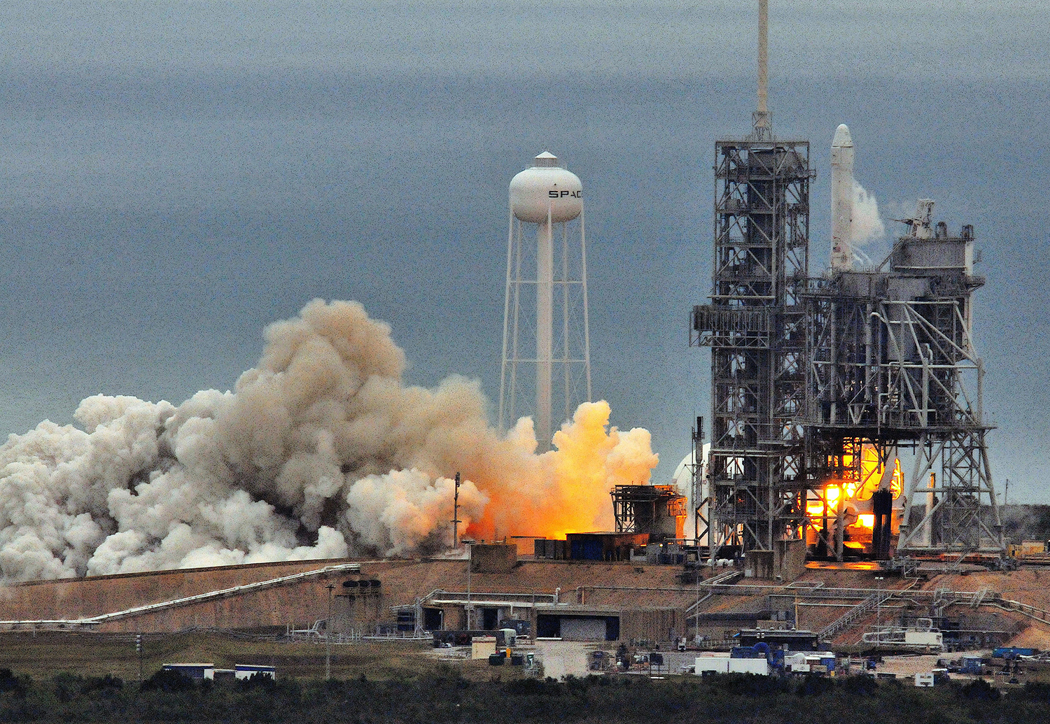
SpaceX was awarded the use of the iconic launch pad and signed a 20 year lease in April of 2014. Since that time SpaceX has already began modifications to the pad area including the construction of a new Horizontal Integration Facility where processing of their boosters and some payload integration will occur. SpaceX is looking at also doing payload integration vertically now as that is a requirement of getting contracts with the U.S. Air Force for launches. The new building is located alongside the crawlerway just before the incline to the hard stand.
The Flame Trench has been modified to accommodate Falcon 9 launches as well. The south side of the Flame Trench was completely filled in; all exhaust from the Falcon 9 launches will be directed out the north end of the trench via the Flame Deflector. That side has been resurfaced with refractory concrete to withstand the intense heat of launches.
The Fixed Service Structure from the Space Shuttle program will be left in place for now. Modifications to accommodate crewed missions and access to the Dragon capsule will be made in the future. The Crew Access Arm from the Shuttle era was removed by NASA, presumably to be preserved for a museum or space facility to display.
New kerosene storage tanks have already been installed on the northeast side of the pad, the Falcon burns rocket grade kerosene (RP-1) and liquid oxygen (LOX), and SpaceX plans to utilize the liquid oxygen tank used by the Shuttle program for their LOX.
Falcon 9 rockets are moved horizontally to the pad on what is called a Transporter/Erector. Rails have been installed from the HIF up to the hard stand to guide the Transporter/Erector to the pad. SpaceX recently tested the new Transporter/Erector at Pad 39A.
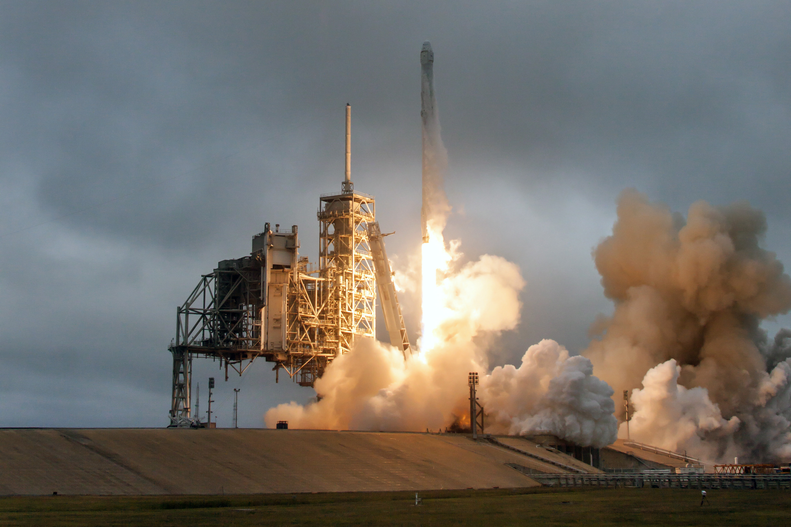
Launching of the Falcon Heavy from Pad 39A has been delayed numerous times over the past year and a half, however Pad 39A was returned to active use recently with the successful launch of the Falcon 9 rocket on Sunday, February 19 on the CRS-10 resupply mission to the International Space Station.
Later this decade, crewed missions once again will blast off from the historic pad. Initially just to the ISS, but SpaceX also has set its sight on establishing a colony on Mars beginning as soon as the following decade.
This article appeared in the 14th issue of RocketSTEM magazine.
Download PDF Issuu Reader Buy Print Edition
